Products
TBC-SH High Accuracy Closed Loop Hall Effect Current Sensor
TBC-SH Series current sensor is a closed loop device uses for precision measurement of DC, AC and pulse current. It can really measure resolution 1000:1. The size of primary doesn’t affect test precision, no matter the location of primary in the hole of current sensor. This series current sensor has rated current input in 500A and 1000A, meansure range upto 2000A. It has 0.1% accuracy, very reliable. Available for appearance customization.
Technology :
Closed loop Hall effectMax. Nominal Value :
±1000AMax. Measuring Range :
±2000AOutput Signal :
± 200mASupply Voltage :
±15~±24VAccuracy :
0.1%Op. Temperature :
-40 °C / 85 °CMounting :
Aperture Φ 40.5mmWeight :
600gMOQ :
32
|
Electrical data (Ta=25℃±5℃) |
|
Type |
TBC500SH |
TBC1000SH |
Unit |
|
Rated input(Ipn) |
±500 |
±1000 |
A |
|
Measure range(Ip) |
±1500 |
±2000 |
A |
|
Turns ratio(Np/Ns) |
1:5000 |
1:5000 |
|
|
Measure resister with±15V |
@±500Amax 0(min) 75(max) |
@±1000Amax 0(min) 15(max) |
Ω |
|
@±1000Amax 0(min) 5(max) |
@±1200Amax 0(min) 5(max) |
Ω |
|
|
Measure resister with±24V |
@±500Amax 0(min) 150(max) |
@±1000Amax 0(min) 50(max) |
Ω |
|
@±1500Amax 0(min) 15max) |
@±2000Amax 0(min) 3 (max) |
Ω |
|
|
Coil resister |
@ +85℃ 60 |
@ +85℃ 50 |
Ω |
|
Rated output(Isn) |
±100±0.1%FS |
± 200±0.1%FS |
mA |
|
Supply voltage |
±15~±24 |
V |
|
|
Power consumption |
≤20+IpX(Np/Ns) |
mA |
|
|
Zero offset |
@Ip=0 ≤±0.2 |
mA |
|
|
Offset drift |
@ -40℃~85℃ ≤±0.5(Typ), ≤±0.75(Max), |
mA |
|
|
Response time |
@100A/μS,10%-90% <1 |
μs |
|
|
Linearity |
@Ip=0-±Ipn ≤0.1 |
%FS |
|
|
Galvanic isolation |
@ 50HZ,AC,1min 6 |
KV |
|
|
di/dt followed |
>100 |
A/μs |
|
|
Bandwidth |
@-3dB DC±150 |
KHz |
|
|
Applications |
AC variable speed drives and servo motor drives
Static converters for DC motor drives
Battery supplied applications
Uninterruptible Power Supplies (UPS)
Switched Mode Power Supplies (SMPS)
Power supplies for welding applications.
|
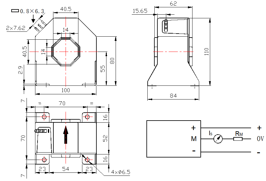
Mechanical dimension(for reference only) |

Remarks:
1. All dimensions are in mm.
2. General tolerance ±0.1mm
|
Directions for use |
1. Is will be in a forward direction when the Ip flows according to the direction of the arrowhead.
2. The primary conductor should be≤120℃.
3. The dynamic performance (di/dt and the response time) is the best when the primary hole is fully filled with the bus bar.
4. The primary turns should be at the top of the sensor for the best magnetic coupling.
5. When measure current flows according to the direction of the arrowhead, Output terminal gets the same phase current
6. When the current will be measured goes through a sensor, the voltage will be measured at the output end.
(Note: The false wiring may result in the damage of the sensor).
7. Custom design in the different rated input current and the output current are available.
|
Further Note |
L/T: Large quantity in 14 days
customized: Support OEM/ODM, Laser marking, Packing
Warranty: 2.5 years
After-sale service: within 24 hours
|
Packing and Shipment |

Add: NO.80 Feitian Avenue, Lukou Street, Jiangning District, Nanjing City
Copyright @2023 Nanjing Token Electronics Science&Technology Co., Ltd. All Rights Reserved. Sitemap | Blog | Xml | Privacy Policy  Network Supported